
This post is about pfSense High Availability
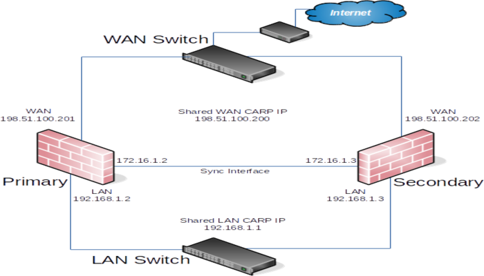
This recipe describes a simple three interface HA configuration. The three interfaces are LAN, WAN, and Sync. This is functionally equivalent to a two interface LAN and WAN deployment, with the Sync interface being used to synchronize configuration and firewall states between the primary and secondary firewalls.
Determine IP Address Assignments
The first task is to plan IP address assignments. A good strategy is to use the lowest usable IP address in the subnet as the CARP VIP, the next subsequent IP address as the primary firewall interface IP address, and the next IP address as the secondary firewall interface IP address. This design is optional, any scheme may be used, but we strongly recommend a consistent and logical scheme to make design and administration simpler.
WAN Addressing – Pfsense High Availability
The WAN addresses will be selected from those assigned by the ISP. For the example in Table WAN IP Address Assignments, the WAN of the HA pair is 198.51.100.0/24, and the addresses 198.51.100.200 through 198.51.100.202 will be used as the WAN IP addresses.
| IP Address | Usage |
|---|---|
| 198.51.100.200/24 | CARP shared IP address |
| 198.51.100.201/24 | Primary node WAN IP address |
| 198.51.100.202/24 | Secondary node WAN IP address |
LAN Addressing
The LAN subnet is 192.168.1.0/24. For this example, the LAN IP addresses will be assigned as shown in Table.
| IP Address | Usage |
|---|---|
| 192.168.1.1/24 | CARP shared IP address |
| 192.168.1.2/24 | Primary node LAN IP address |
| 192.168.1.3/24 | Secondary node LAN IP address |
Sync Interface Addressing
There is no shared CARP VIP on this interface because there is no need for one. So, these IP addresses are used only for communication between the firewalls. For this example, 172.16.1.0/24 is used as the Sync subnet. Only two IP addresses will be used, but a /24 is used to be consistent with the other internal interface (LAN). For the last octet of the IP addresses, use the same last octet as that firewall’s LAN IP address for consistency.
| IP Address | Usage |
|---|---|
| 172.16.1.2/24 | Primary node Sync IP address |
| 172.16.1.3/24 | Secondary node Sync IP address |
Installation, interface assignment and basic configuration
Install the OS on the firewalls as usual and assign the interfaces identically on both nodes. Interfaces must be assigned in the same order on all nodes exactly. So, if the interfaces are not aligned, configuration synchronization and other tasks will not behave correctly. If any adjustments have been made to the interface assignments, they must be replicated identically on both nodes.
Then, connect to the GUI and use the Setup Wizard to configure each firewall with a unique hostname and non-conflicting static IP addresses.
For example, one node could be “firewall-a.example.com” and the other “firewall-b.example.com”, or a more personalized pair of names.
The default LAN IP address is 192.168.1.1. Each node must be moved to its own address, such as 192.168.1.2 for the primary and 192.168.1.3 for the secondary. So, this layout is shown in Once each node has a unique LAN IP address, then both nodes may be plugged into the same LAN switch.
Setup Sync Interface
Before proceeding, the Sync interfaces on the cluster nodes must be configured. the addresses to use for the Sync interfaces on each node. Once that has been completed on the primary node, perform it again on the secondary node with the appropriate IPv4 address value.
To complete the Sync interface configuration, you have to add the firewall rules on the both nodes to allow synchronization.
At a minimum, the firewall rules must pass the configuration synchronization traffic (by default, HTTPS on port 443) and pfsync traffic. In most cases, a simple “allow all” style rule is enough.

Configure pfsync – Pfsense High Availability
State synchronization using pfsync must be configured on both the primary and secondary nodes to function.
First on the primary node and then on the secondary, perform the following:
- Navigate to System > High Avail Sync
- Check Synchronize States
- Set Synchronize Interface to SYNC
- Set pfsync Synchronize Peer IP to the o
- ther node. Set this to
172.16.1.3when configuring the primary node, or172.16.1.2when configuring the secondary node - Click Save
On the primary node only, perform the following:
- Navigate to System > High Avail Sync
- Then, set Synchronize Config to IP to the Sync interface IP address on the secondary node,
172.16.1.3 - Set Remote System Username to
admin.
- Set Remote System Password to the admin user account password, and repeat the value in the confirmation box.
- Check the boxes for each area to synchronize to the secondary node. For this guide, as with most configurations, all boxes are checked. The Toggle All button may be used to select all of the options at once, rather than selecting them individually.
- Click Save
- As a quick confirmation that the synchronization worked, on the secondary node navigate to Firewall > Rules on the SYNC tab. The rules on the primary are now there, and the temporary rule is not anymore.
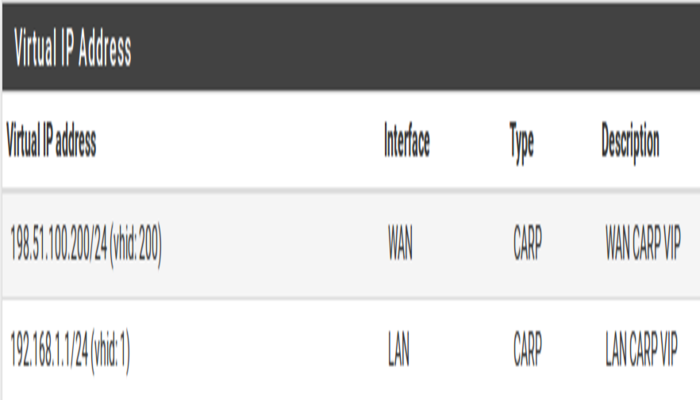
Configuring the CARP Virtual IPs
- Navigate to Firewall > Virtual IPs on the primary node to manage CARP VIPs
- Click
 Add at the top of the list to create a new VIP.
 - The LAN VIP would be set similarly except it will be on the LAN interface and the address will be
192.168.1.1
If there are any additional IP addresses in the WAN subnet that will be used for purposes such as 1:1 NAT, port forwards, VPNs, etc, they may be added now as well.
Click Apply Changes after making any edits to the VIPs.
After adding VIPs, check Firewall > Virtual IPs on the secondary node to ensure that the VIPs synchronized as expected.
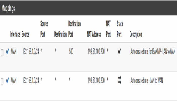
Configure Outbound NAT for CARP
The next step will be to configure NAT so that clients on the LAN will use the shared WAN IP as the address.
- Navigate to Firewall > NAT, Outbound tab
- Click to select Manual Outbound NAT rule generation
- Click Save
A set of rules will appear that are the equivalent rules to those in place for Automatic Outbound NAT. Adjust the rules for internal subnet sources to work with the CARP IP address instead.
- Click
 to the right of the rule to edit
 - Locate the Translation section of the page
- Select the WAN CARP VIP address from the Address drop-down
- Change the Description to mention that this rule will NAT LAN to the WAN CARP VIP address
Modifying the DHCP Server – Pfsense High Availability
The DHCP server daemons on the cluster nodes need adjustments so that they can work together. The changes will synchronize from the primary to the secondary, so as with the VIPs and Outbound NAT, these changes need only be made on the primary node.
- Navigate to Services > DHCP Server, LAN* tab.
- Set the DNS Server to the LAN CARP VIP, here
192.168.1.1 - Then, set the Gateway to the LAN CARP VIP, here
192.168.1.1 - Set the Failover Peer IP to the actual LAN IP address of the secondary node, here
192.168.1.3 - Click Save
So, setting the DNS Server and Gateway to a CARP VIP ensures that the local clients are talking to the failover address and not directly to either node. This way if the primary fails, the local clients will continue talking to the secondary node.
Finally, the Failover Peer IP allows the daemon to communicate with the peer directly in this subnet to exchange data such as lease information. When the settings synchronize to the secondary, this value is adjusted automatically so the secondary points back to the primary.
So, this post was about Pfsense High Availability